 Data Recovery using the STB Suite
Introduction
This article will discuss methods which can be used leveraging several STB Suite functions which can be used to try to recover data from a problem disk drive.
Of course there are some limitations or conditions which must be met to have any hope of retrieving data. The main thing is that the drive needs to be “alive” enough that it shows up on the test machine. Also, the drive must be able to be started or spun up.
There are also limitations you should be aware of that have to do with the type of drive you are trying to recover data from. SAS, Fibre Channel, and SCSI drives all have robust retry and error correction features which are configurable by the user. Unfortunately SATA drives do not have these configurable features. We will cover the details of setting up SAS,SCSI, or Fibre Channel drives later in this article.
Goals
The main goal is to get as much data off of the problem drive and onto a new or known good drive. Some of the goals along the way are:
- Set up the problem drive to do the maximum error correction and retries
- Set up the problem drive and the STB Suite to not abort the recovery process if errors occur
Setting up error correction and retries
For SCSI, SAS, & Fibre Channel drives we will use the Mode Page editor functions of the STB Suite to configure the problem drive before we attempt the data recovery operation. The Mode Page edit function is accessed by:
- starting the STB Suite in Original single-drive mode
- Right-clicking on the problem drive in the device display
- Choosing the Edit Mode Pages choice from the Quick Command list
- Setting the various Mode Pages
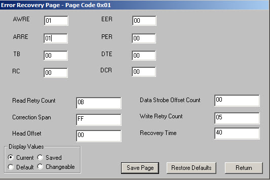
The Error Recovery Mode Page (Page 0x01)
As the name implies, Mode Page 0x01 contains the settings that the drive will act upon when an error occurs during a Read or Write command. We want to set the values on this page to tell the drive to use as many retries as it needs and to use as much error correction as is possible to try to successfully complete all Read commands.
Here are the definitions of the various settings:
ARRE (Automatic Read Reallocation Enabled) bit
0 An automatic read reallocation enabled (ARRE) bit set to zero specifies that the device server shall not perform automatic reallocation of defective logical blocks during read operations.
1 An ARRE bit set to one specifies that the device server shall enable automatic reallocation of defective logical blocks during read operations. All error recovery actions required by the error recovery bits (i.e., the EER bit, the PER bit, the DTE bit, and the DCR bit) shall be processed. The automatic reallocation shall then be performed only if the device server successfully recovers the data. The recovered data shall be placed in the reallocated logical block. The device server shall report any failures that occur during the reallocation operation. Error reporting as specified by the error recovery bits (i.e., the EER bit, the PER bit, the DTE bit, and the DCR bit) shall be performed only after completion of the reallocation operation.
TB (Transfer Block) bit
0 A transfer block (TB) bit set to zero specifies that the device server shall not transfer a logical block to the data-in buffer if the logical block is not recovered within the recovery limits specified.
1 A TB bit set to one specifies that the device server shall transfer a logical block to the data-in buffer before returning CHECK CONDITION status if the logical block is not recovered within the recovery limits specified. The data returned in this case is vendor-specific. The TB bit does not affect the action taken for recovered data.
RC (Read Continuous) bit
0 A read continuous (RC) bit set to zero specifies that error recovery operations that cause delays are acceptable during the data transfer. Data shall not be fabricated.
1 An RC bit set to one specifies the device server shall transfer the entire requested length of data without adding delays to perform error recovery procedures. This implies that the device server may send data that is erroneous or fabricated in order to maintain a continuous flow of data. The device server shall assign priority to the RC bit over conflicting bits within this byte.
Note. Fabricated data may be data already in a buffer or any other vendor-specific data. The RC bit may
be used in image processing, audio, or video applications.
EER (Enable Early Recovery) bit
1 An enable early recovery (EER) bit set to one specifies that the device server shall use the most expedient form of error recovery first.
0 An EER bit set to zero specifies that the device server shall use an error recovery procedure that minimizes the risk of error mis-detection or mis-correction. This bit only applies to data error recovery and it does not affect positioning retries.
Note. An EER bit set to one may imply an increase in the probability of error mis-detection or mis-correction. An EER bit set to zero allows the specified retry limit to be exhausted prior to using error correction codes.
PER (Post Error) bit
1 A post error (PER) bit set to one specifies that if a recovered read error occurs during a command performing a read or write operation, then the device server shall terminate the command with CHECK CONDITION status with the sense key set to RECOVERED ERROR. If the DTE bit is set to one, then the PER bit shall be set to one
0 A PER bit set to zero specifies that if a recovered read error occurs during a command performing a read or write operation, then the device server shall perform error recovery procedures within the limits established by the error recovery parameters and only terminate the command with CHECK CONDITION status if the error becomes uncorrectable based on the established limits.
DTE (Data Terminate On Error) bit
1 A data terminate on error (DTE) bit set to one specifies that the device server shall terminate the data-in or data-out buffer transfer upon detection of a recovered error.
0 A DTE bit set to zero specifies that the device server shall not terminate the data-in or data-out buffer transfer upon detection of a recovered error.
DCR (Disable Correction) bit
1 A disable correction (DCR) bit set to one specifies that ECC shall not be used for data error recovery.
0 A DCR bit set to zero allows the use of ECC for data error recovery. If the EER bit is set to one, the DCR bit shall be set to zero.
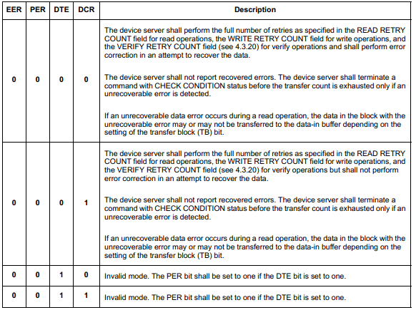
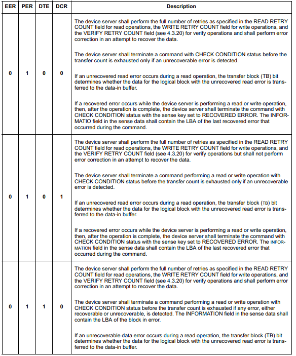
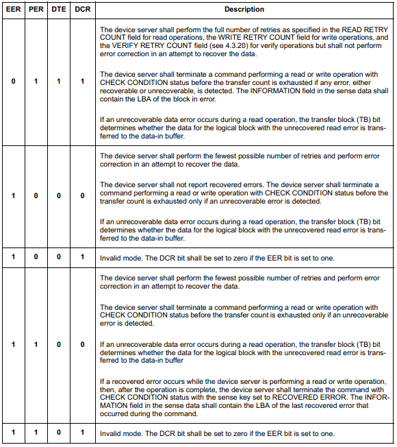
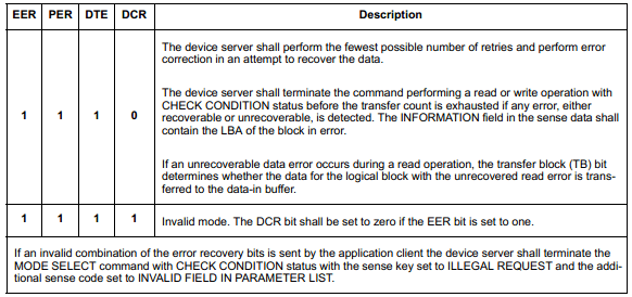
The combinations of the error recovery bits (i.e., the EER bit, the PER bit, the DTE bit, and the DCR bit) are
explained in the tables below.
Recommended Settings
To allow the drive to try everything at its disposal to read all the data that it can we recommend the following settings:
TB = 1, RC = 0, EER = 0, PER = 0, DTE = 0, DCR = 0
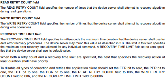
Set the Read Retry Count and the Recovery Time to the highest number the drive allows.
Copying data from the problem drive
We will use the STB Suite Original Mode Media Duplication function to copy data from the problem drive onto a new drive.
This function is accessed via the Original Mode Disk->Media Duplication menu choice
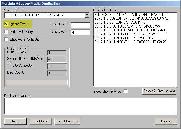
The most important setting for this function is the Ignore Errors check box. Checking this box will allow the duplication process to continue if there are any errors.
The Start and End Block fields allow you to specify a block range to copy, the default (End Block = -1) defines the copy to start at the first block and continue through to the last block on the source (problem) drive.
Use the drop-down button to select your source drive. This will be the problem drive that you are trying to recover data from. Then select one or more destination drives from the Destination Devices field.
When using the Media Duplication function for data recovery it is usually not useful to do checksum verification.
Start the copy process by clicking the Start Copy button, watch the progress in the Copy Progress fields, keep your fingers crossed and hope for the best!